Ask Latest Price
Active Member
9 Years

Mitech CO.,LTD.
MITECH CO,.LTD Create Value for Customer, Make Contribution for World’s Security.

Add to Cart
Instrument Features
Adopt microcomputer control, with reasonable internal structure, beautiful appearance, small size, light weight;
Structure design is more lightweight, operate conveniently on-site;
With over temperature protection device, the controller will automatically cut off the high voltage ,to avoid damaging the X - ray tube due to high temperature;
mA (mA) stable unit can change with X ray tube filament voltage to adjust the unidirectional pulse frequency, to ensure the stability of X ray tube current ;
KV (kV) control unit can continuously control the tube voltage level, to adapt to the radiography requirements of different material ;
Anti interference circuit can effectively reduce the high voltage impulse of X ray generator to control system;
Complete protection functions and the fault types can be displayed;
The working time and rest time of the detector is in strict accordance with the proportion of 1:1;
Delayed high pressure start function, convenient for the operator to leave the dangerous area;
The high pressure and control are isolated to keep the generator work more safe and reliable;
Special testing power grid and voltage function,suitable for generator unit
Standard Configuration
| NO. | Name | QTY | Remarks |
| 1 | X ray flaw detector | 1 | |
| 2 | controller | 1 | |
| 3 | Connection cable(10 cores) | 1 | |
| 4 | Power cable(2 cores) | 1 | |
| 5 | Ground lead | 1 | |
| 6 | Fuse(3A) | 5 | |
| 7 | Attached files | 1 |
The Emission of X-ray

Figure 1 Figure 2
Figure 3 Figure 4
Figure 1:Glass tube circumferential target generator
Figure 2:Ceramic tube directional generator
Figure 3:Glass tube circumferential cone target generator
Figure 4:Glass tube directional generator
Working Conditions
| Environment temperature | -25℃-40℃ |
| Relative humidity | <85% |
| Safe work pressure | 0.35-0.50mPa |
Note, Do not use when the pressure is under 0.35mPa
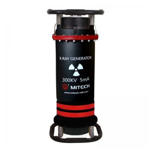
Generator Appearance
1 Gas pressure gauge 2 Cable line socket
3 Caution light 4 X ray generate area
5 Cooler fan
Controller Appearance
1 Fault code and exposure chart 2 Standby light
3 HV light 4 Digital display
5 Time knob 6 KV presetting knob
7 “HV on” key 8 “HV off” key
9 Power switch 10 Connection cable socket
11 Power cable socket 12 Earthing wire
13 Fuse holder(3A)
The main parts in the controller are:KV control panel, mA control panel, microcomputer control panel, protection board, Controllable silicon high voltage module, LC filter, main,assistant silicon control inverter system. The inner controller has cooling fans, vent-windows on the side and back.